+86 15303735673
 Jessica@frpzs.com
 Technical Data

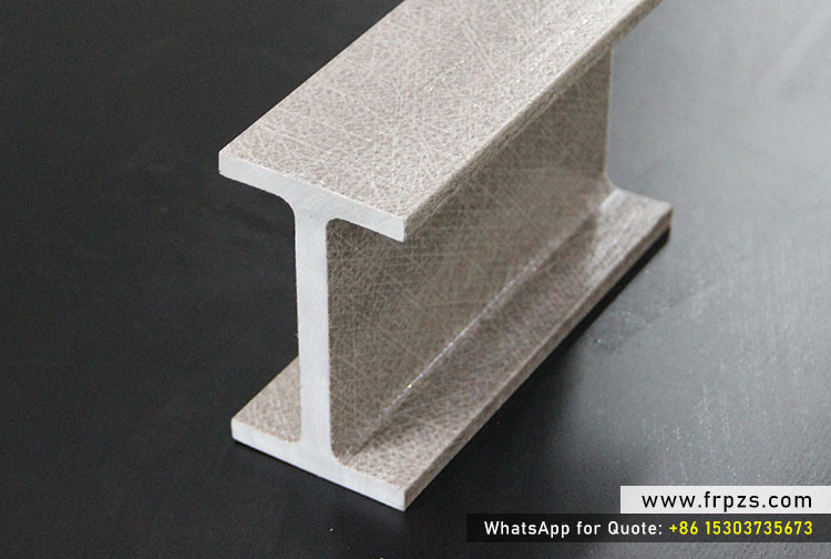
How to Design with FRP I Beams: Load, Span and Structural Considerations
FRP I beams (also known as fiberglass H beams or pultruded FRP I beams) are increasingly used in industrial structures, walkways, platforms, and infrastructure projects. However, proper structural design is essential to fully utilize their mechanical advantages.
This guide explains key design considerations when using FRP I beams, including load types, span limits, stiffness requirements, and safety factors, helping engineers and project owners select the correct FRP structural solution.
Understanding FRP I Beam Structural Behavior
Unlike steel I beams, FRP I beams are anisotropic materials. Their strength and stiffness are highest in the longitudinal (pultrusion) direction due to continuous glass fiber reinforcement.
Key mechanical properties typically considered in design include:
- Tensile strength and modulus
- Compressive strength
- Flexural strength and stiffness
- Shear performance
For verified mechanical performance, engineers should always refer to third-party tested data such as ASTM-tested FRP I beam reports.
Typical Loads Applied to FRP I Beams
| Load Type | Description | Design Notes |
|---|---|---|
| Dead Load | Self-weight of beam and permanent fixtures | FRP beams reduce dead load due to low density |
| Live Load | People, equipment, moving loads | Often governs flexural design |
| Environmental Load | Wind, snow, seismic effects | Important for outdoor and elevated structures |
| Impact Load | Forklifts, dropped tools | Consider safety factors and deflection limits |
Span and Deflection Control
In FRP structural design, deflection often governs beam selection rather than ultimate strength. FRP I beams have lower elastic modulus than steel, making stiffness control critical.
| Application | Typical Deflection Limit |
|---|---|
| Walkways & Platforms | L/200 – L/250 |
| Industrial Flooring | L/180 – L/200 |
| Cable Trays | L/150 – L/180 |
Proper span-to-depth ratio selection can significantly improve service performance and user comfort.
Safety Factors for FRP I Beam Design
Due to long-term creep behavior and environmental exposure, FRP structures are typically designed using higher safety factors than steel.
| Design Aspect | Recommended Safety Factor |
|---|---|
| Flexural Strength | 2.5 – 3.0 |
| Compression | 2.0 – 2.5 |
| Connections & Supports | 3.0+ |
Using conservative safety factors ensures long-term structural reliability in aggressive environments.
Connection Design Considerations
Connections are often the most critical part of FRP I beam structures. Common connection methods include:
- Bolted connections with stainless steel fasteners
- FRP connection plates and brackets
- Hybrid steel-FRP connection systems
Avoid excessive drilling near beam edges and always consider bearing and shear stresses around bolt holes.
Why Engineers Choose FRP I Beams
- Excellent corrosion resistance in chemical and marine environments
- Lightweight for faster installation and reduced foundation loads
- Electrical insulation and non-sparking properties
- Low maintenance over long service life
With proper design and verified mechanical data, FRP I beams provide a reliable alternative to steel in many structural applications.
Need Tested FRP I Beam Data?
For projects requiring verified mechanical performance, refer to our independently tested FRP I beam properties:
Intertek Tested FRP I Beam Mechanical Properties
Our team also provides customized FRP I beam sizes, pultrusion molds, and complete FRP production lines.
Contact Us for FRP Structural Solutions
Website: www.frpzs.com
Email: Jessica@frpzs.com
WhatsApp: +86 153 0373 5673
We support engineers and project owners with advanced FRP structural design solutions.
complete FRP I beam technical guide