+86 15303735673
 Jessica@frpzs.com
 Technical Data

What Is FRP Pultrusion?
Pultrusion is a continuous, automated manufacturing process used to produce fiber-reinforced polymer (FRP) profiles with a constant cross-section. The term is derived from the combination of "pull" and "extrusion" — unlike extrusion, where material is pushed through a die, pultrusion pulls the fiber-resin composite through a heated steel forming die.
The result is a lightweight, high-strength structural profile — I-beams, channels, hollow tubes, solid rods, custom shapes — used across construction, electrical infrastructure, transportation, marine, and chemical processing industries. Pultruded FRP profiles offer excellent corrosion resistance, electrical non-conductivity, dimensional consistency, and a high strength-to-weight ratio that rivals steel at a fraction of the mass.
This guide walks through every stage of the pultrusion process in production order, including quality control checkpoints, critical process parameters, and diagnostic solutions for common manufacturing defects.
FRP Pultrusion at a Glance
- Process type: Continuous thermoset composite manufacturing
- Primary reinforcement: E-glass fiber roving (55–70% volume fraction)
- Resin systems: Unsaturated polyester (UP), vinyl ester (VE), epoxy
- Pull speed: 0.2–2.0 m/min depending on cross-section
- Die temperature: 80–180°C across three heated zones
- Degree of cure: ≥90% measured by DSC
- Key standard: GB/T 1446–1453 (mechanical testing)
Raw Material Preparation
Every high-quality pultruded profile begins with carefully selected and prepared raw materials. The three primary components — fiber reinforcement, resin system, and release agent — must meet strict specification before production starts.
Glass Fiber Roving
Standard pultrusion uses E-glass (alkali-free) fiber roving as the primary structural reinforcement. Rovings are multi-filament bundles wound onto cylindrical packages and mounted on the creel rack. Critical requirements include:
- Moisture content: ≤0.05% (excess moisture causes resin cure inhibition and void formation)
- Clean, contaminant-free surface with a compatible silane sizing
- Consistent linear density (tex) across all packages in a production run
Surface reinforcements such as continuous strand mat (CSM) or surface veil (typically C-glass or polyester) may be added to improve surface finish, UV resistance, or corrosion protection in the final profile.
Resin System
The resin system encapsulates the fibers, transfers load between them, and determines the profile's chemical and thermal resistance. Common systems include:
- Unsaturated polyester (UP): Most economical; widely used for general structural and civil engineering profiles
- Vinyl ester (VE): Superior corrosion resistance; preferred for chemical processing and marine environments
- Epoxy: Highest mechanical properties and adhesion; used in aerospace, wind energy, and demanding structural applications
The resin is blended with an initiator (catalyst) — typically organic peroxide — and an accelerator to tune gel time and cure profile for the target die temperature and pull speed. Fillers such as calcium carbonate (CaCO₃) or aluminum trihydrate (ATH) may be added for cost reduction, flame retardancy, or surface smoothness. Resin viscosity at 25°C should be in the range of 200–600 mPa·s to ensure adequate fiber wet-out.
Release Agent
Release agents are critical to prevent the cured profile from bonding to the die bore. They are applied either as an internal mold release (IMR) — blended directly into the resin — or as an external mold release applied to the die bore surface. Most production lines use both for optimal die release and surface quality.
Fiber Arrangement & Creel Setup
The creel rack holds all roving packages and feeds them forward with controlled, uniform tension. Proper creel setup directly determines the mechanical performance and dimensional consistency of the finished profile.
Roving packages are loaded onto spindles and threaded through tension control guides. Target roving tension is 5–15 N per bundle, with a tolerance of ±10% across all positions. Uneven tension causes fiber waviness, asymmetric cross-sections, and profile twist — one of the most difficult defects to correct in production.
After the creel, rovings pass through guide boards (forming plates) that organize the fiber bundles into the geometric pattern required by the product cross-section. Any surface veil or mat layers are introduced at this stage, layered over or beneath the roving array. The assembly then enters the resin bath as a structured, cohesive fiber stack.
Resin Impregnation
Achieving complete and uniform fiber wet-out is the single most critical factor in producing void-free, high-strength pultruded profiles. Impregnation occurs in either an open resin bath or a closed injection box.
Open Resin Bath
The traditional method: fiber bundles are submerged in a trough of catalyzed resin at 20–35°C and drawn over and under a series of impregnation rollers, which mechanically force resin between individual filaments. The rollers also squeeze out excess resin, helping control the final resin content (30–45% by weight).
Resin bath temperature is tightly controlled — higher temperatures lower viscosity and improve wet-out but also accelerate gel time, reducing the pot life available for impregnation. Bath level is maintained by continuous resin feed, and viscosity is monitored at regular intervals.
Closed Injection Box
An increasingly preferred alternative for environmental compliance and resin consistency, the closed injection box forces resin under pressure directly into the fiber bundle at the die entry, entirely enclosing the impregnation zone. Key advantages include:
- Near-elimination of styrene VOC emissions (critical for occupational health compliance)
- More consistent resin content across the profile cross-section
- Reduced resin waste and simplified cleanup
- Better suited to reactive resin systems with short pot lives
Preforming
After the resin bath, the wet fiber assembly is passed through a series of forming plates (preformer) that progressively consolidate the impregnated fibers into the exact geometry of the die bore entry. This stage performs several critical functions:
- Geometry transition: Plates with progressively smaller apertures gradually shape the wet bundle from a loose fiber array into a near-net-shape preform
- Excess resin removal: Surplus resin is squeezed out, helping set the final resin-to-fiber ratio before the die
- Reinforcement consolidation: Mat layers and surface veils are pressed flush against the roving core, eliminating wrinkles and air pockets
- Tension equalization: The preformer corrects minor tension imbalances from the creel before the fiber stack enters the heated zone
Preforming is especially important for complex cross-sections such as I-beams, channels, and hollow box profiles, where maintaining precise fiber placement and layer sequence through the die bore is essential to achieving design mechanical properties.
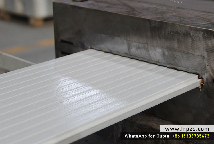
Thermal Curing in the Pultrusion Die
The pultrusion die is the heart of the process — a precision-machined steel tool that simultaneously forms the final cross-section geometry and initiates the chemical cure of the resin matrix. Die design and temperature control are the primary levers governing profile quality, production speed, and die service life.
Die Construction
Pultrusion dies are typically fabricated from tool steel (commonly P20 or H13 grade) with a hard chrome-plated bore. The bore surface finish is ground to a roughness of Ra ≤ 0.4 μm — a critical specification that minimises friction pull-force, prevents surface marking, and extends die service life. Die length typically ranges from 600 to 1,500 mm depending on profile wall thickness and target pull speed: thicker profiles require longer dies to ensure sufficient dwell time for complete cure.
Three-Zone Temperature Profile
Most production dies are divided into three independently controlled heating zones that create a deliberate temperature gradient along the die length:
| Zone | Function | Typical Temperature |
|---|---|---|
| Zone 1 — Preheat | Raise fiber-resin temperature; initiate resin flow into remaining fiber voids | 80–100°C |
| Zone 2 — Gel | Trigger gelation; cross-linking begins; resin transitions from liquid to gel | 120–150°C |
| Zone 3 — Cure | Complete cross-linking; profile reaches structural integrity; exotherm peak occurs | 140–180°C |
A key technical challenge is managing the exothermic cure reaction. As the resin cross-links, it releases heat — in thick-section profiles, this exotherm can cause the core temperature to substantially exceed the die wall temperature. If the exotherm peak exceeds approximately 220°C, thermal degradation and longitudinal cracking become probable. Resin system formulation, pull speed, and zone temperatures must be balanced to keep the exotherm within safe limits.
Caterpillar Haul-off
The caterpillar haul-off unit (also called the pull unit or traction system) is the driving force of the entire process. It grips the cured profile emerging from the die and pulls the entire fiber-resin assembly — from creel to die exit — at a constant, controlled speed.
Most modern haul-off systems use dual hydraulic caterpillar clamps: two opposing sets of rubber-padded traction pads that grip the profile symmetrically from above and below (or from both sides for asymmetric sections). The clamping force is controlled to provide sufficient traction without surface marking or dimensional distortion of the profile.
Pull speed is one of the most influential process parameters:
- Higher speed increases output but reduces dwell time in the die — demanding higher die temperatures or a more reactive resin formulation to achieve complete cure
- Lower speed provides more cure time but increases production cost per metre and can cause over-cure if die temperatures are not reduced proportionally
- Thin-walled profiles (≤3 mm wall) can typically be pultruded at 1.0–2.0 m/min; thick solid sections (≥12 mm) are often limited to 0.2–0.5 m/min
Pull speed and die temperature are interdependent parameters that must be set together as a matched pair for each profile and resin system — changing one without adjusting the other will compromise cure quality or surface finish.
Precision Cutting (Flying Saw)
As the cured profile exits the haul-off, it passes to the flying saw (also called the cut-off saw or travelling saw), which cuts the continuous profile into specified lengths without stopping the line. The saw carriage accelerates to match the profile's pull speed, makes the cut, then returns to its start position for the next cycle — enabling truly continuous production.
Saw blade selection is critical: diamond-coated or tungsten-carbide-tipped blades are standard for FRP profiles, producing clean, low-burr cuts while minimising heat generation and fibre pull-out. The cut face must be perpendicular to the profile axis, with an angular deviation of no more than 0.5°.
FRP cutting generates glass-fibre dust — a respiratory hazard requiring mandatory dust extraction at the cut point, and personal protective equipment (PPE) including respirators and eye protection for all nearby personnel. Dust must be captured and disposed of as an industrial waste per applicable local regulations.
Post-processing & Inspection
Final inspection ensures every profile dispatched to customers meets dimensional, visual, and mechanical specifications. A structured inspection protocol typically covers four areas:
Visual Inspection
Every profile is examined for surface defects including voids, cracks, dry-fibre spots, resin-rich zones, surface crazing, and discolouration. Profiles are classified under controlled lighting conditions. A first-grade visual acceptance rate of ≥98% is a standard industry benchmark.
Dimensional Inspection
Cross-sectional dimensions, wall thickness, straightness (bow and sweep), and twist are measured and compared against drawing tolerances. For structural profiles, typical dimensional tolerances follow EN 13706 (Europe) or ASTM D3917 (North America) unless otherwise specified by the customer.
Mechanical Testing (Sampling)
Test specimens cut from production batches are tested per GB/T 1446–1453 (Chinese national standards, widely referenced in international manufacturing) for:
- Tensile strength and modulus (longitudinal and transverse)
- Flexural strength and modulus
- Compressive strength
- Interlaminar shear strength (ILSS)
Mechanical test results should meet or exceed 95% of the design values specified in the product data sheet.
Post-cure (Optional)
Where maximum mechanical performance or dimensional stability is required — particularly for epoxy-based systems — profiles may undergo a free-standing post-cure in an oven at 80–120°C for 2–4 hours to drive degree of cure above 95%.
Packing & Traceability
Accepted profiles are wrapped in moisture-barrier film, fitted with protective end caps, and bundled for shipment. Each bundle is labelled with the product code, batch number, production date, and applicable standard — essential for full supply-chain traceability and quality audit purposes.
Key Process Parameters for FRP Pultrusion
The following table summarises the critical process parameters that production engineers monitor and control during pultruded FRP profile manufacturing:
| Parameter | Typical Range | Notes |
|---|---|---|
| Pull Speed | 0.2–2.0 m/min | Higher for thin-wall profiles; must be matched to die temperature |
| Die Temperature (Cure Zone) | 140–180°C | Depends on resin system; epoxy typically needs higher temps |
| Resin Content (by weight) | 30–45% | Control tolerance ±2%; higher resin = lower stiffness |
| Fiber Volume Fraction | 55–70% | Higher fiber volume = higher strength and stiffness |
| Die Bore Surface Roughness | Ra ≤ 0.4 μm | Hard chrome plated; critical for friction and surface finish |
| Degree of Cure | ≥90% | Measured by DSC; post-cure can raise to ≥95% |
| Resin Viscosity (25°C) | 200–600 mPa·s | Lower viscosity improves wet-out; monitor with Brookfield viscometer |
| Roving Tension | 5–15 N per bundle | Tolerance ±10%; uneven tension causes profile twist |
Common Defects in FRP Pultrusion — Causes & Solutions
Even well-established pultrusion lines encounter recurring defect patterns. The following table covers the most frequently reported issues, their root causes, and recommended corrective actions:
| Defect | Primary Causes | Corrective Actions |
|---|---|---|
| Surface Voids / Pinholes | Resin viscosity too high; air entrapment in bath; inadequate wet-out | Lower bath temperature to reduce viscosity; switch to injection box; slow pull speed |
| Dry Fibre Spots (White Patches) | Insufficient impregnation pressure; roving tension too high; resin starvation | Increase bath depth or injection pressure; reduce tension; replenish resin bath |
| Longitudinal Cracking | Excessive exotherm; cure rate too fast for cross-section; die temperature too high | Reduce die temperature; reformulate catalyst level; slow pull speed to extend gel time |
| Profile Twist | Asymmetric fiber layout; uneven roving tension; off-centre guide plate | Rebalance creel tension; realign guide plates; verify forming plate geometry |
| Surface Roughness | Release agent failure; die bore wear; resin-rich surface layer delaminating | Re-apply external release agent; re-chrome die bore; check surface veil continuity |
| Fibre Waviness | Uneven creel tension; premature gelation before die entry; turbulence in bath | Equalise tension; reduce accelerator; check bath roller alignment |
| Delamination at Cut Ends | Insufficient cure; worn saw blade; cut-force vibration | Verify degree of cure ≥90% before cutting; replace blade; reduce feed rate |